Yes, you can charge a portable power station with solar panels, transforming sunlight into stored electrical energy for off-grid power. Modern portable power stations include built-in charge controllers designed to accept solar input, making them compatible with various solar panel configurations. This renewable energy solution works for camping trips, emergency backup power during outages, and any situation requiring electricity away from the grid.
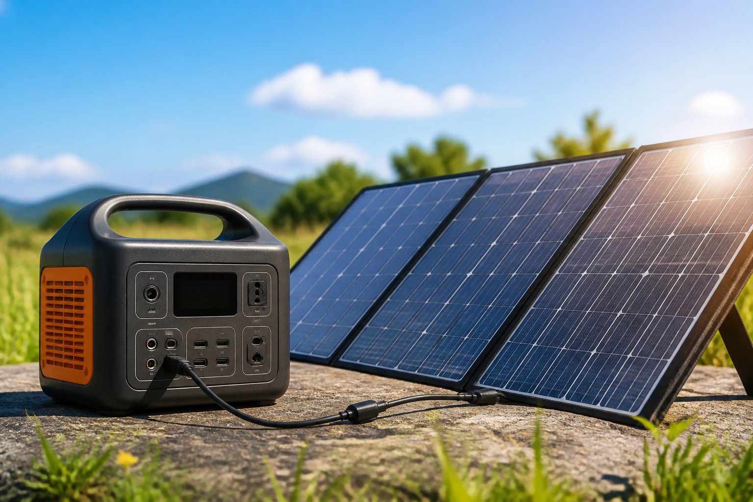
The process requires matching compatible solar panels to the power station’s specifications, connecting them properly, and positioning the panels for maximum sun exposure. While the concept sounds simple, real-world solar charging involves understanding voltage ranges, wattage limits, connector types, and environmental factors that impact charging speed. Many people underestimate how effectively solar panels can charge these devices when set up correctly.
This guide covers everything needed to successfully charge a portable power station using solar panels. From verifying compatibility between panels and stations to optimizing placement for faster charging times, readers will learn the practical steps and technical considerations that make solar charging efficient and reliable in actual outdoor conditions.
Solar Charging Fundamentals for Portable Power Stations
Solar panels convert sunlight into direct current electricity that flows into the power station’s battery through a built-in charge controller, which regulates voltage and current to protect the battery. The efficiency of this process depends on the type of charge controller used and how well it matches the battery chemistry inside the station.
How Solar Panels Power a Portable Power Station
Solar panels generate DC electricity when photons strike their silicon cells, creating an electrical current that flows through the panel’s positive and negative terminals. This current travels through a cable into the portable power station’s solar input port, where it reaches the internal solar charge controller. The charge controller acts as a gatekeeper, adjusting the incoming voltage and current to levels the battery can safely accept.
Most portable power stations include MC4, XT60, or Anderson connectors for solar input. The panel’s open-circuit voltage (Voc) must fall within the station’s acceptable voltage range, typically between 11-150V depending on the model. If the Voc is too low, the station will not charge. If it exceeds the maximum voltage limit, the charge controller may be damaged.
The power station’s display shows real-time solar input in watts, which fluctuates based on sun angle, shade, and panel temperature. A 200W panel rarely delivers its full rated output in real conditions, typically producing 120-180W depending on environmental factors.
Solar Charge Controller Types: MPPT vs. PWM
Portable power stations use either MPPT (Maximum Power Point Tracking) or PWM (Pulse Width Modulation) charge controllers to manage solar input. MPPT controllers actively adjust their input voltage to extract maximum power from the panels, operating at 20-30% higher efficiency than PWM controllers. They convert excess voltage into additional current, making them ideal for panels with higher voltage than the battery’s charging voltage.
PWM controllers simply match the panel voltage to the battery voltage without conversion, resulting in wasted potential power when panel voltage exceeds battery voltage. Budget power stations under 500Wh typically use PWM controllers, while mid-range and premium models include MPPT controllers. An MPPT controller charging a LiFePO4 battery might harvest 400W from panels that would only deliver 300W through a PWM controller under the same conditions.
The battery management system (BMS) works alongside the charge controller to monitor cell voltage, temperature, and current during solar charging.
Role of Battery Chemistry in Solar Charging
Lithium iron phosphate (LiFePO4) batteries accept solar charging more efficiently than other lithium chemistries due to their stable voltage curve and higher charge acceptance rates. LiFePO4 batteries can handle charge rates up to 1C (capacity in one hour), meaning a 1000Wh LiFePO4 power station can safely accept 1000W of solar input if its charge controller supports it.
The BMS regulates charging by monitoring individual cell voltages and temperatures, reducing input power if cells become unbalanced or overheated. LiFePO4 batteries charge at a constant current until reaching approximately 90% capacity, then switch to constant voltage mode for the final 10%. This two-stage charging extends battery lifespan but means the last 10% charges slower than the first 90%.
Battery chemistry also determines minimum charging temperatures. LiFePO4 batteries should not charge below 0°C (32°F) without internal heating, as lithium plating can occur and permanently damage cells. The BMS blocks solar charging when temperatures fall outside safe ranges.
Matching Solar Panels to Your Power Station
A solar panel will only charge a power station if its electrical output falls within the station’s solar input specs. Voltage, wattage, and current limits must all align, and the physical connector must match or be adapted.
Understanding Solar Input Specifications
Every portable power station publishes solar input specifications that define what kind of panel array it can accept. The three critical parameters are input voltage range, maximum solar input wattage, and maximum input current.
The input voltage range defines the minimum and maximum voltage the station’s MPPT controller can handle. If a panel’s working voltage falls below the minimum, the controller won’t start charging. If the panel’s open-circuit voltage exceeds the maximum, the station may shut down or suffer damage. Most mid-sized stations accept 11–60V, while larger units may support up to 150V.
Maximum solar input is the wattage ceiling for all connected panels combined. Exceeding this limit doesn’t damage the station, but the MPPT controller will only draw what it can handle. The excess capacity goes unused.
Maximum input current sets the amperage limit for the solar input circuit. This is less commonly listed but matters when wiring high-current panels in parallel.
Panel Wattage and Maximum Solar Input
Panel wattage determines how quickly a power station charges, but only up to the station’s max solar input ceiling. A station rated for 400W maximum solar input will regulate any larger array down to 400W.
Oversizing the panel array by 20–30% above the station’s max solar input is good practice. Real-world conditions rarely deliver 100% of a panel’s nameplate wattage due to temperature losses, suboptimal angles, and irradiance variation. A 500W array on a 400W-capable station helps maintain consistent charging at the station’s full capacity throughout the day.
Undersizing panels extends charge time proportionally. A 200W panel array on a 2,000Wh station at 70% derate delivers roughly 140W, requiring about 14 hours of good sun for a full charge. Doubling the array to 400W cuts charge time in half.
Open-Circuit Voltage and Maximum Input Current
Open-circuit voltage (Voc) is the voltage a solar panel produces with nothing connected. It represents the highest voltage the power station will see and is the safety-critical number for compatibility checks.
Most portable power stations list a maximum input voltage, typically 30V, 60V, or 150V depending on the model. The panel’s Voc must stay below this limit. In cold weather below 32°F, Voc can rise 10–20% because semiconductor voltage increases as temperature drops. The standard safety margin is multiplying Voc by 1.2 to account for cold conditions. A panel with 50V Voc reaches 60V in freezing temperatures, which exceeds a 60V-limited station and risks overvoltage shutdown or damage.
Voltage at maximum power (Vmp) is the actual working voltage when the panel delivers its rated wattage. This must fall within the station’s MPPT voltage range, typically between the minimum and maximum input voltage. A panel with 18V Vmp won’t charge a station with a 30V minimum unless wired in series with another panel.
Maximum input current limits the total amperage from all connected panels. This specification is less often published but becomes relevant when wiring multiple high-current panels in parallel. Exceeding the current limit can trip overcurrent protection or cause the station to throttle input power.
Connector Types and Adapter Cables
DC solar input connectors vary widely across portable power stations. No industry standard exists, so matching the physical connector is as important as matching electrical specs.
MC4 connectors are the most common on standalone solar panels. MC4 is the residential solar industry standard, used by 12 of 20 panels in our database. However, most portable power stations do not accept MC4 directly and require an adapter cable.
XT60 and XT60i are barrel-style connectors used by EcoFlow and Anker stations. XT60i is rated for higher current above 8A. Most EcoFlow and Anker panels ship with MC4-to-XT60 adapter cables included.
DC barrel connectors like the DC8020 (8mm barrel) are proprietary to specific brands. Jackery uses DC8020 on its Explorer stations and SolarSaga panels. Third-party panels require a compatible adapter cable to connect.
Aviation-style plugs are used by Bluetti on models like the AC200L. These proprietary connectors require brand-specific adapter cables for use with non-Bluetti panels.
Anderson Powerpole connectors appear on some older or specialty panels but are rare in the portable power station market.
Adapter cables are available for most connector combinations and cost $15–40. Using an adapter adds a junction point where water intrusion or contact resistance can occur, so inspect connections periodically. Buying panels from the same brand as the power station eliminates adapter needs and potential compatibility issues.
Configuring and Connecting Solar Panels
Proper wiring configuration directly impacts charging efficiency and protects the power station from electrical damage. Understanding voltage limits and connection types ensures optimal power delivery while preventing costly mistakes.
Series vs. Parallel Wiring
Series wiring connects solar panels end-to-end, adding their voltages together while maintaining the same current. A series connection works well when users need to reach higher voltages to match their power station’s input voltage range. For example, two 20V panels in series produce 40V at the same amperage as a single panel.
Parallel wiring connects all positive terminals together and all negative terminals together. This configuration adds current while keeping voltage constant. Parallel connection suits situations where voltage requirements are already met but more current is needed for faster charging.
The choice between series vs parallel depends on the power station’s specifications. Most portable power stations specify a maximum input voltage (often 12V to 60V) and maximum current rating. Users should check these limits before configuring their array to avoid equipment damage.
Achieving Efficient Connections
Quality cables minimize cable loss and voltage drop during charging. Using cables that are too thin or too long creates resistance that wastes energy as heat. Cables should match the current rating of the solar array, with thicker gauge wire for higher currents.
MC4 connectors are standard for solar panel connections and provide weatherproof, secure links. Adapters allow compatibility between different connector types when mixing brands. Each connection point should be tight and protected from moisture to maintain conductivity.
The power station’s charge controller handles voltage conversion automatically through MPPT technology. Users simply need to ensure their combined panel output falls within the specified input voltage range. Clean connections without corrosion or loose fittings ensure maximum power transfer.
Avoiding Voltage and Current Issues
Exceeding the maximum input voltage damages the charge controller permanently. Users must calculate total voltage in series configurations carefully, accounting for open-circuit voltage rather than nominal voltage. Solar panels can produce 20% higher voltage than rated in cold, bright conditions.
Staying within the current limit prevents overheating and potential shutdown of the charging system. Most power stations have built-in protection, but relying on it repeatedly reduces component lifespan. Matching the solar array output to manufacturer specifications ensures safe, efficient operation.
Monitoring voltage during initial setup verifies correct configuration before damage occurs. A multimeter confirms that series connections don’t exceed limits and parallel connections distribute current properly.
Optimizing Solar Charging for Real-World Efficiency
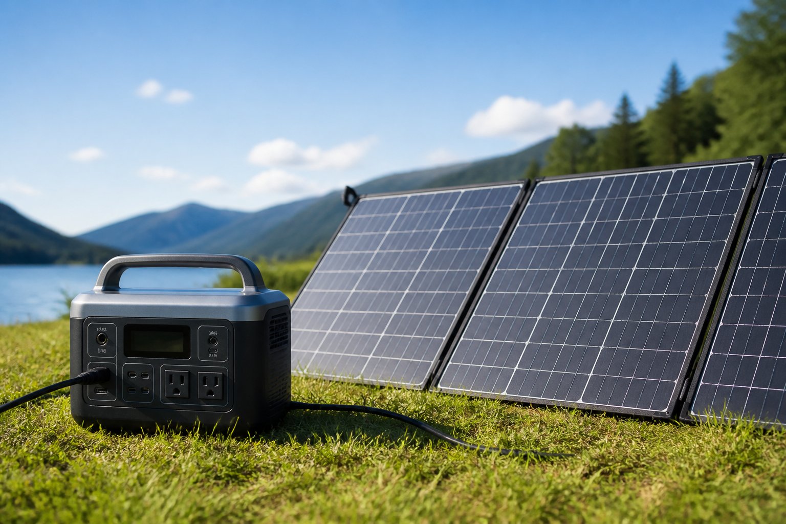
Getting the most from solar panels requires attention to placement, environmental conditions, and realistic expectations about charging speed. Small adjustments in panel angle and location can boost charging efficiency by 30% or more compared to casual setups.
Panel Placement and Angle
Panel placement directly affects how much solar irradiance reaches the cells. In the Northern Hemisphere, panels should face south. In the Southern Hemisphere, they should face north.
Panel angle should roughly match the site’s latitude for year-round use. A location at 35° latitude benefits from a 35° tilt. During summer months, reducing the angle by 10–15° captures overhead sun better. In winter, increasing the tilt by 10–15° helps.
Adjusting the panel every 2–3 hours during peak sun hours maximizes output. Most foldable panels include kickstands for quick angle changes. Users who keep panels flat on the ground lose 20–40% of potential energy compared to properly angled setups.
Avoid these common mistakes:
- Placing panels on hot surfaces like car hoods or metal roofs
- Leaving panels completely flat unless the sun is directly overhead
- Forgetting to account for the sun’s movement across the day
A solar tracker automatically follows the sun’s path and can increase daily energy harvest by 25–35%. For portable setups, manual adjustment every few hours provides a practical middle ground.
Factors Affecting Charging Performance
Solar panel efficiency depends on cell type, temperature, and cleanliness. Monocrystalline panels typically reach 20–23% efficiency, while polycrystalline models stay around 15–18%.
Panel temperature affects output significantly. For every 1°C above 25°C (77°F), most panels lose 0.3–0.5% efficiency. Keeping panels cool through airflow underneath helps maintain performance. Avoid sealing the back against solid surfaces.
Dust, pollen, and water spots block light. A thin layer of dust can reduce output by 5–10%. Wiping panels with a microfiber cloth before each use restores full capacity.
Key performance factors:
| Factor | Impact on Efficiency |
|---|---|
| Dust or dirt buildup | -5% to -15% |
| High panel temperature (>45°C) | -10% to -20% |
| Poor cable connections | -3% to -8% |
| Incorrect panel angle | -20% to -40% |
Cable resistance also matters. Longer or thinner cables waste energy as heat. Using the shortest cable that still allows proper positioning reduces losses.
Dealing With Partial Shading and Cloud Cover
Partial shading creates disproportionate power loss. If shade covers just 10% of a panel, total output can drop by 50% or more. This happens because solar cells connect in series, and the weakest cell limits current flow.
Shade avoidance is critical. Check for shadows from trees, buildings, tents, or gear throughout the day. Shadows that seem small in the morning can grow larger by afternoon.
Cloud cover reduces solar irradiance but doesn’t stop charging completely. Thin clouds may cut output to 30–50% of full capacity. Heavy overcast conditions reduce it to 10–20%. Bifacial panels perform better in cloudy weather by capturing diffuse light from both sides.
When clouds pass frequently, charging efficiency becomes unpredictable. Monitoring the power station’s input display helps users understand real-time performance. Some days require twice as long to reach the same charge level compared to clear conditions.
Real-World Charging Times and Efficiency
Real-world charging times rarely match manufacturer claims. A 200W panel under ideal laboratory conditions may only deliver 140–160W in typical field use.
Real-world efficiency depends on:
- Time of day (peak sun hours between 10 AM and 2 PM produce the most power)
- Season (winter sun angles reduce output by 30–50% compared to summer)
- Geographic location (areas closer to the equator receive more consistent sunlight)
- Weather patterns (coastal fog, humidity, and pollution all reduce clarity)
For a 500Wh power station with a 200W panel under good conditions, expect 3.5–4.5 hours to full charge. The same setup on a partly cloudy day may take 7–9 hours.
Sample real-world charging times:
| Power Station Capacity | Panel Wattage | Clear Sky | Partly Cloudy |
|---|---|---|---|
| 300Wh | 100W | 3.5–4 hours | 7–8 hours |
| 500Wh | 200W | 3–4 hours | 6–8 hours |
| 1000Wh | 200W | 6–7 hours | 12–14 hours |
Users should plan for lower output than rated wattage. Assuming 70–80% of panel capacity in calculations provides more accurate time estimates and reduces frustration during trips or emergencies.
Choosing Solar Panel and Power Station Brands
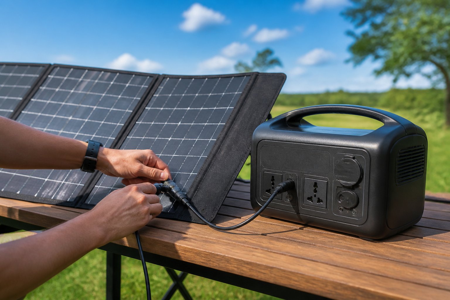
Brand selection affects charging speed, connector compatibility, and long-term reliability. Most manufacturers offer proprietary panels designed for their power stations, though third-party options can work with the right adapters and voltage matching.
Integrated and Third-Party Panel Options
Manufacturers like Jackery, EcoFlow, and Bluetti produce solar panels specifically engineered for their portable power stations. These integrated systems eliminate guesswork around voltage compatibility and include matching connectors that plug directly into the unit without adapters.
Jackery’s SolarSaga series pairs seamlessly with their Explorer models, while EcoFlow’s solar panels connect directly to the Delta and River lineups. Bluetti offers PV120 and PV200 panels optimized for their AC series power stations.
Third-party panels provide flexibility and often cost less than brand-specific options. Users can connect panels from companies like Renogy, Goal Zero, or generic monocrystalline panels if the voltage falls within the power station’s input range and the proper adapter cable is used. The main challenge involves matching MC4, XT60, Anderson, or DC barrel connectors to the specific input port on the power station.
Popular Models and Compatibility
The EcoFlow Delta 2 accepts 11-100V solar input and charges at up to 500W, making it compatible with most 100W-400W portable panels. The EcoFlow Delta Pro supports up to 1,600W solar input when using dual charging cables, suitable for serious off-grid setups or whole-home backup scenarios.
Bluetti AC200P handles 12-145V input at 700W maximum, working well with both the brand’s 200W panels and third-party alternatives in the 100-200W range. Users frequently pair multiple panels in series to reach higher wattage thresholds faster.
Jackery’s Explorer 1000 charges efficiently with their 100W SolarSaga panels, and users can connect up to two panels in parallel for 200W total input.
Pass-Through Charging and Off-Grid Applications
Pass-through charging allows a solar generator to charge its internal battery while simultaneously powering devices. EcoFlow Delta series and Bluetti models support this feature, making them practical for extended off-grid setups where continuous power supply is necessary.
For whole-home backup applications, the EcoFlow Delta Pro combined with high-wattage solar arrays can recharge during daylight hours while running essential appliances. This capability reduces reliance on grid power during extended outages.
Users should verify that their chosen power station explicitly supports pass-through charging, as some budget models disable output during solar charging to protect battery health. This limitation affects usability in continuous-use scenarios like camping trips or job sites.